L’équipe E.S.C.Ro.C.S. participe à la coupe de robotique chaque année depuis 2020. Nous avons présenté à cette compétition divers robots, avec plus ou moins de succès en fonction des années. Nous étions partie d’une base Arduino très simple en 2020-2021 puis avons progressivement évolué vers des architectures plus complexes à base d’ESP32 et de diverses cartes filles communiquant sur un bus.

Une discussion autour d’un café entre deux escrocs a fait naitre une idée un peu folle : et si on faisait un robot sans aucun ordinateur, sans micro-contrôleur, sans même la moindre électronique numérique, c’est possible ? On trouve de nombreux robots analogiques sur le net, mais ils sont en général limités à des fonctions très simples : suivie de ligne, de son, de lumière, etc. Peut-on faire un robot complexe, programmable, mais sans programmation d’ordinateur ?
Le retour de la cassette audio
Il semble assez évident qu’en l’absence de logique programmable, il sera très difficile de faire un robot capable de prendre des décisions à la volée et d’adapter sa trajectoire de manière dynamique. On choisit de se limiter à la conception d’un robot de type « automate » qui exécutera une succession linéaire d’actions de jeu. Bien que celà puisse sembler limitant, dans les faits, la majorité, et possiblement 80% des équipes de la coupe adoptent une stratégie similaire. Ça peut suffire même pour atteindre les huitièmes voire les quarts de finales.
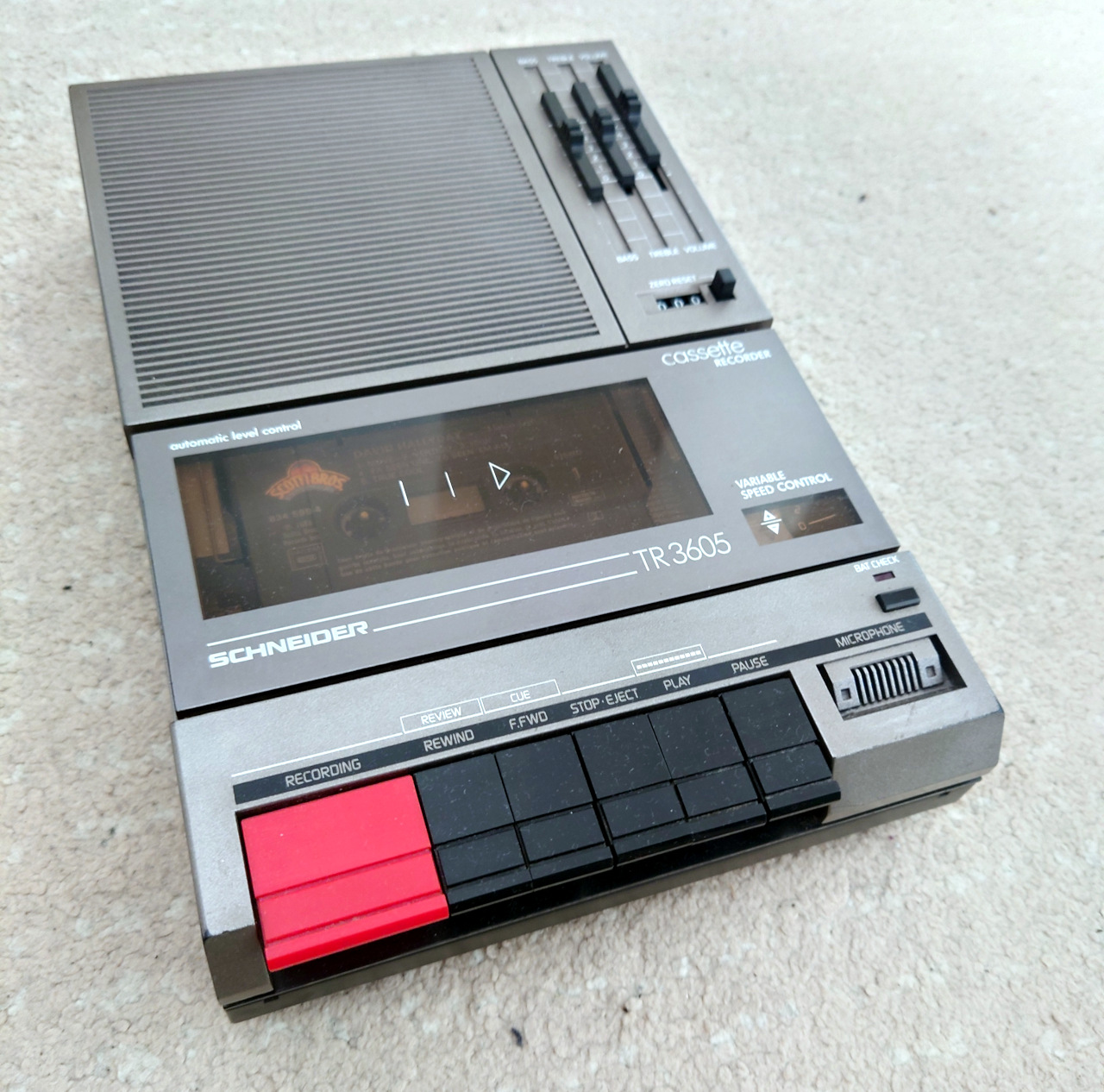
Mais même un robot automate qui exécute de manière séquentielle une suite de mouvement nécessite une forme de mémoire pour stocker cette séquence. Tout comme l’orgue de barbarie utilise un carton perforé pour jouer les bonnes notes, il nous faut trouver un support. On le veut analogique, par principe. Il doit être lisible et réinscriptible facilement de manière électronique. Le support le plus évident est la bande magnétique : un magnétophone avec sa cassette audio semble parfaitement convenir à notre besoin. Nous avons donc acheté un magnifique Schneider 3605 sorti tout droit d’un « labo de langue » du siècle dernier.
Plutôt AM ou FM ?
Mais quoi stocker sur cette cassette, et comment ? Listons déjà l’ensemble des informations à enregistrer :
- Notre robot est un robot différentiel à deux roues. Il a donc deux degrés de liberté (gauche/droite ou alors avancer/tourner, ce qui revient au même). Il y a donc 2 signaux analogiques à enregistrer sur la cassette.
- Il doit être également capable d’actionner des moteurs, de lever des bras, de démarrer des pompes, etc. Le choix d’actionneurs à utiliser dépend du règlement de la coupe qui sera annoncé en septembre. Cependant, la plupart de ces actionneurs bougent entre deux états (haut/bas, ouvert/fermé, ventousé/lâché, etc.). On intuite donc qu’on aura besoin de stocker une information de type « tout ou rien » et d’avoir plusieurs canaux à disposition.
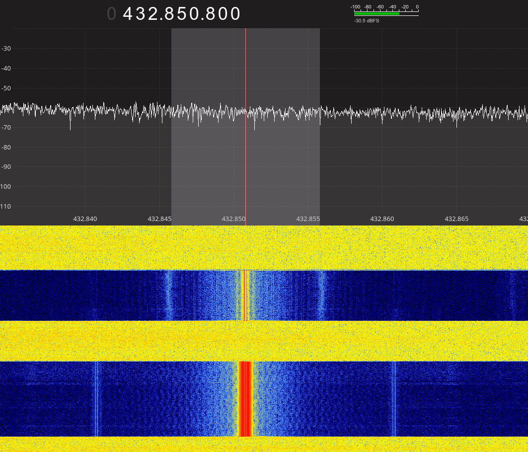
Notre magnétophone, comme la plupart des lecteurs/enregistreurs de cassettes de taille modeste est mono. On peut donc exclure la possibilité d’enregistrer deux ondes simultanément. Il faut donc attribuer des bandes de fréquences à ces signaux et les moduler. Notre choix se porte sur des modulations de fréquence : une modulation d’amplitude serait extrêmement sensible à des variations de gain de l’amplificateur, une modulation de phase serait facilement brouiller par l’effet « wow et flutter » inhérent aux lecteurs de cassettes. La modulation de fréquence est à la fois simple à mettre en œuvre et robuste. Le lecteur permet un rendu de la plage de fréquence de 100 Hz à 8 kHz environ. On attribue alors les fréquences suivantes :
- Signal analogique de translation de 1kHz à 2kHz. La valeur 1.5kHz représentant le zéro, et les valeurs 1kHz et 2kHz représentent -5V et +5V.
- Signal analogique de rotation de 4kHz à 8kHz.
- Signaux tout-ou-rien à placer dans la bande 100Hz-1kHz.
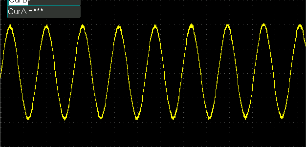
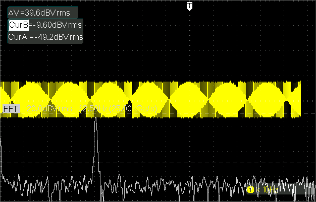
Avant de se lancer tête baissée dans la réalisation de cartes électroniques, j’ai d’abord commencé par effectuer des essais sur ordinateur : un bout de code Python permet de générer un son, celui-ci est enregistré sur la cassette, celle-ci est rembobinée, relue et réenregistrée sur le PC. La suite GNURadio permet d’implémenter facilement une démodulation et vérifier que le signal est bien lisible. Les résultats initiaux semblent prometteurs et on arrive à reconstituer les signaux d’entrée.
Le plomb, matériau d’avenir
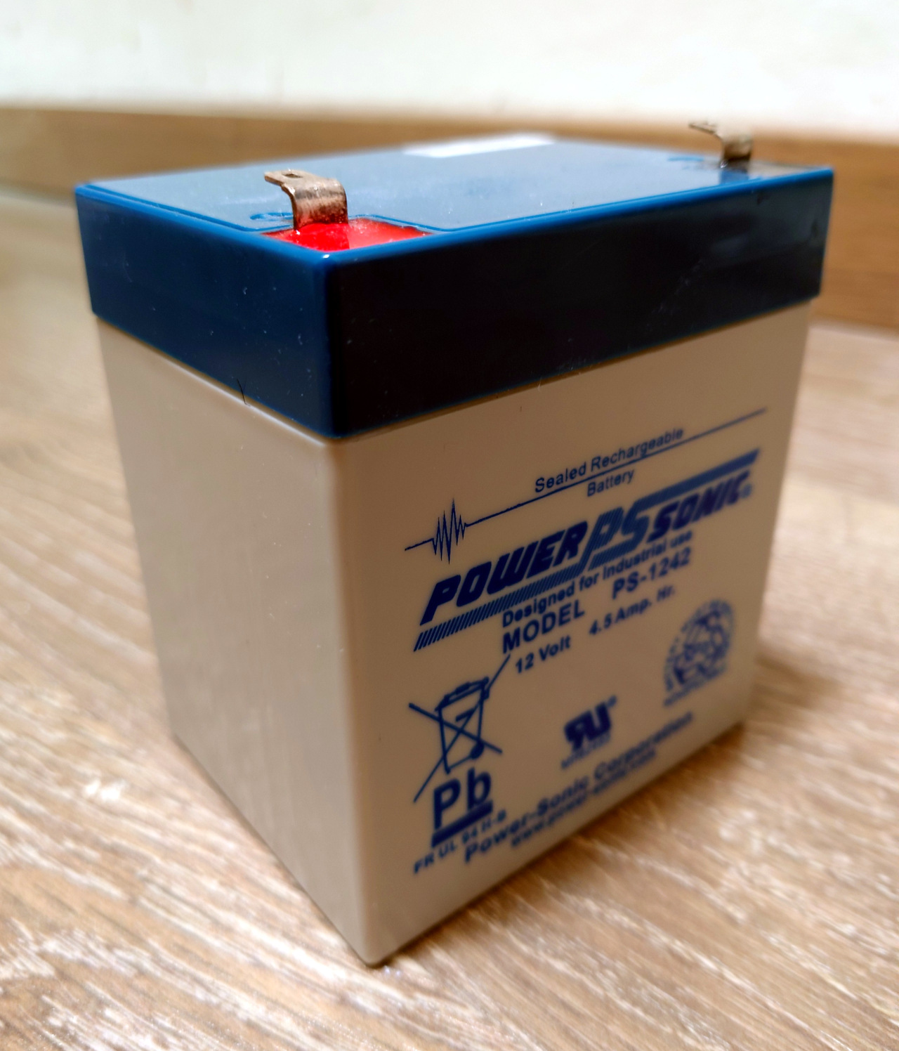
Le choix de la technologie de batterie est évident. Les batteries au plomb ont un facteur « cool » indéniable. En plus de ça, les batteries lithium, pour des raisons de sécurité nécessite d’utiliser un BMS pour suivre les niveaux de courant, les températures et les tensions de cellule. Les BMS du commerce sont tous basés sur des microcontrôleurs et réaliser un BMS analogique serait une « quête annexe » coûteuse. Le plomb, c’est très bien.
Les batteries au plomb ont une tension de 13.8V lorsqu’elles sont chargées et environ 12V lorsqu’elles ne sont plus bonnes à rien pour un robot. Dans un soucis de simplicité, tous les moteurs et actionneurs seront pris de sorte à pouvoir être connectés directement à ces niveaux de tension. Nous utilisons depuis des années des moteurs EMG30, motoréducteurs 12V avec encodeurs à effet Hall, et ils marchent très bien pour la coupe. L’électronique analogique a quant à elle besoin d’une tension régulée très propre. De plus, une alimentation à rails positifs et négatifs simplifieront la conception de circuits à amplificateurs opérationnels (mes composants préférés). Le choix se porte donc sur une alimentation +5V / -5V avec un rail 0V de référence de tension. Cela permet d’utiliser un régulateur linéaire depuis la tension de batterie jusqu’à 10V, puis de générer le rail médian. Pas d’alimentations à découpage, pas de bruit.
Beaucoup trop de cartes
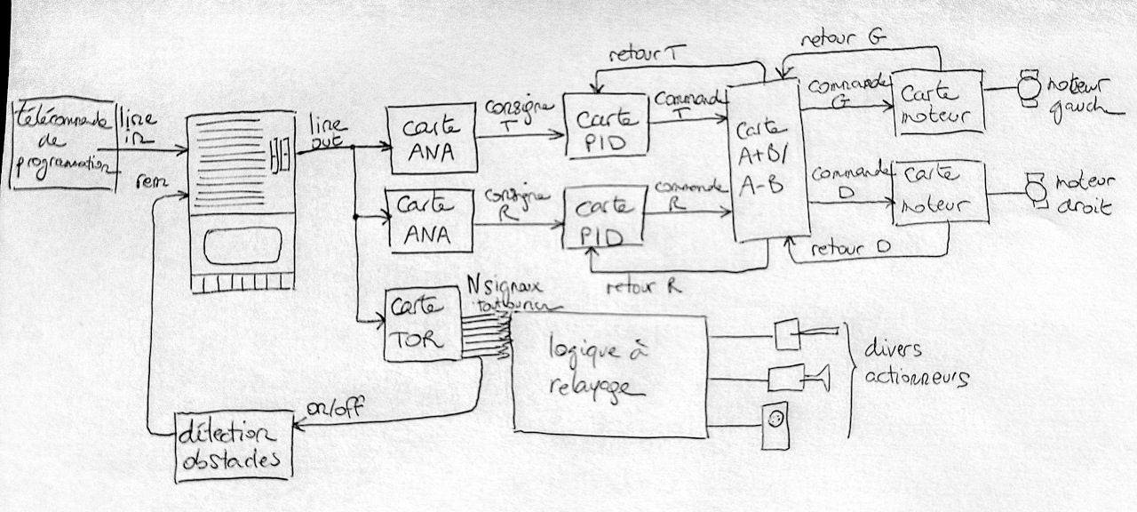
L’achitecture électronique du robot est centrée autour du lecteur cassette. Celui-ci s’interface avec le robot via sa sortie audio « line out ». L’entrée « line in » pour l’enregistrement permettra d’enregistrer les stratégies sur la cassette. L’idée est la suivante : sur une table d’essai, une télécommande spécialement conçue est branché sur l’entrée audio du magnétophone. Nous pouvons ensuite piloter le robot avec le télécommande, à la façon d’un robot pour la coupe junior. L’ensemble des mouvements du robot sera alors enregistré sur la bande. En match, il n’y aura plus qu’à rejouer la séquence pour obtenir un robot autonome.
Le sortie audio est ensuite envoyée vers deux cartes de démodulation analogique, une pour le signal de translation, une pour la rotation. Le seul but de ces cartes est de générer des signaux analogiques de vitesse entre -5V et +5V (0V signifiant arrêté, une valeur positive avancer, une valeur négative reculer). Ces signaux sont donné à des cartes d’asservissement PID, qui, à partir du retour de vitesse des codeurs rotatifs, calculent la commande de rotation et de translation. Les commandes gauche et droite sont définies par addition et soustraction des commandes de rotation et de translation. Ça permet également de gérer le choix du côté où jouer, en intervertissant les canaux gauche et droite. La carte moteur génère ensuite un signaux PWM dont le rapport cyclique est proportionnel à la commande et qui commute l’alimentation des moteurs dans un pont en H. Les encodeurs à effet Hall génèrent un signal dont la fréquence est proportionnel à la vitesse de rotation et la carte moteur effectue cette conversion fréquence vers tension.
Les différents signaux tout-ou-rien pour les actionneurs permettent de commander les différents moteurs via d’éventuelles logiques à relayage si des comportement plus complexes sont nécessaire, par exemple pour couper le moteur si un fin de course est atteint.
Enfin, on n’oubliera pas qu’une condition d’homologation des robots est la faculté du robot à éviter les collisions avec l’adversaire. La détection peut se faire de manière classique avec un capteur analogique à infrarouge ou à ultrason. On évitera le beau lidar qui ferait tâche sur un tel robot. Le magnétophone est équipé d’un port fort sympathique : le contrôle à distance « rem » qui permet de forcer la pause de la cassette en fermant un circuit entre deux contacts d’un connecteur Jack. Ça permet de réaliser simplement l’évitement « du pauvre » (ou plutôt celui des 3/4 des équipes) : tout couper en cas d’obstacle et reprendre quand la voie est libre.
Conclusion
Tout ça n’est évidement que théorique, tant que le robot n’est pas construit et ne roule pas, on ne peut pas savoir si ce projet est réellement viable. On en saura plus dans les mois à venir.
Et on espère bien avoir à nouveau le stand « K7 » l’an prochain…
